|
Logic Synthesis
Sum-of-products and product-of-sums expressions are
common solutions to Boolean problems, but often they
are far from parsimonious solutions. On the other hand, limiting
oneself to the use of just AND-OR-NOT might not be the right
approach to finding good solutions to more complex problems. With
GeneXproTools you can use an extremely wide spectrum of logical
functions (a total of 258 built-in functions plus all kinds
of user defined functions) to design your logic circuits.
And, for instance, if you are just interested in NAND-only or
NOR-only circuits, you might try and find a solution to your problem
using just this particular function instead of applying De Morgan's
theorem to your sum-of-products solutions to design your circuits:
as is often the case a more parsimonious expression can be found.
And if you are interested in less conventional circuits, say a MUX-only circuit or a AND-XOR-NOT circuit, GeneXproTools has no
problems working with just these functions to build your circuits.
In this section we briefly introduce
the most important tools you have at
your disposal in GeneXproTools to design
all kinds of minimal logic circuits.
 |
Loading Data (Truth Tables) |
Before designing a logic circuit with GeneXproTools you must first load the
truth tables for the learning algorithm. The data screening engine of GeneXproTools checks the validity of all the
truth tables and is operative every time you load your
truth tables
either for training or testing. Only the values of False and True
(case insensitive) or "0" and "1" are valid as
input.
Data Sources & Formats
GeneXproTools allows you to import your truth tables from
Excel & databases, text files and
GeneXproTools files.
Excel Files & Databases
The loading of data from Excel/databases requires making
a connection with Excel/database and then selecting the
worksheets or columns of interest. By default GeneXproTools will set
the last column as the output or response variable, but you can easily set any of the other columns
as response variable by selecting the variable of interest and then
checking Response in the context menu.
Only the values of False and True (case insensitive) or "0" and "1" are valid as input.
Note, however, that GeneXproTools uses 0's and 1's internally and, therefore,
False and True are respectively converted into "0" and "1" and shown in this format.
Text Files
For text files GeneXproTools supports three
commonly used data matrix formats.
The first is the standard Records x Variables
(Response Last) format where records are
in rows and variables in columns, with the output or response variable occupying the
last column. In the small example below with eight records,
Y is the function output and A, B, and C are
the input or predictor variables:
A B C Y
0 0 0 0
0 0 1 0
0 1 0 0
0 1 1 1
1 0 0 0
1 0 1 1
1 1 0 1
1 1 1 1
And the second is the Gene Expression Matrix format commonly used
in DNA microarrays studies where
records are in columns and
variables in rows, with the function output occupying the
first row. For instance, in Gene Expression
Matrix format, the truth table above corresponds to:
Y 0 0 0 1 0 1 1 1
A 0 0 0 0 1 1 1 1
B 0 0 1 1 0 0 1 1
C 0 1 0 1 0 1 0 1
This kind of format is the standard for
datasets with a relatively small number of records and thousands of
variables. Note, however, that this format is not
supported for Excel files and if your data is kept in this format in Excel, you must
copy it to a text file and then use this file to load your data into GeneXproTools.
GeneXproTools uses the Records x
Variables format internally and therefore all
kinds of input format are automatically
converted and shown in this format in
the Data Panel and Scoring Panel.
GeneXproTools supports the standard
separators (space,
tab, comma, semicolon, and pipe) and detects them automatically. The
use of labels to identify your variables is optional and
GeneXproTools also detects automatically whether they are
present or not. However, if you use them you will be able to
generate more intelligible code with each variable
clearly identified by
its name.
GeneXproTools Files
GeneXproTools files can be very convenient to use as
data source as they
allow the selection of exactly the same datasets
used in a particular run. This can be very useful especially if
you want to use the same datasets across different runs.
Loading Data Step-by-Step
To Load Input Data for Modeling
- Click the File Menu and then choose New.
The New Run Wizard appears. You must give a name to your new run file (the default filename extension of
GeneXproTools run files is .gep) and then choose
Logic Synthesis in the Problem Category box and the kind of source file
in the Data Source Type box.
GeneXproTools allows you to work both with Excel
& databases, text
files and gep files.
- Then go to the Entire Dataset (or Training
Set) window by clicking the Next button.
Choose the path for the dataset by browsing the Open dialog
box and choose the appropriate data matrix format. Irrespective
of the data format used,
GeneXproTools shows the loaded data in the standard
Records x
Variables (Response Last) format, with the
output variable occupying the
last column.
- Then go to the Validation/Test Data window by clicking the Next button.
Repeat the same steps of the previous point if
you wish to use a specific validation/test set. The loading of
a specific validation/test set is optional as
GeneXproTools allows you to split your data into
different datasets for training and
testing/validation in the Dataset
Partitioning window.
- Click the Finish button to save your new run file.
The Save As dialog box appears and after choosing the directory where you want your new run file to be saved, the
GeneXproTools modeling environment appears.
Then you just have to click the Start button to create a
logic circuit as
GeneXproTools automatically chooses from a gallery of templates default settings that will enable you to evolve a
logic circuit with just a click.
 |
Choosing the Fitness Function |
For Logic Synthesis
problems, in the Fitness
Function Tab of the
Settings Panel you have
access to a a total of
21
built-in fitness
functions, most of which combine multiple objectives, such as the use
of different reference simple models, cost matrix,
parsimony pressure, variable pressure, and
a few more.
Additionally, you can also design your own
custom fitness functions and explore the solution space with
them.
By clicking the Edit Custom Fitness button, the Custom
Fitness
Editor is opened and there you can write the code of
your fitness function in JavaScript.
The kind of fitness function you choose will depend most probably on the
cost function
or error measure you are most familiar
with. And although there is nothing wrong with this,
for all of them can accomplish an efficient
evolution, you might want to try different fitness
functions for they travel the fitness landscape
differently: some of them very straightforwardly in
their pursuits while others choose less travelled
paths, considerably enhancing the search process.
 |
Choosing the Function Set |
GeneXproTools allows you to choose your function set
from a total of 258
built-in
logical functions and an unlimited number of
custom functions, designed using the JavaScript language in the GeneXproTools environment.
Built-in Logical Functions
GeneXproTools offers a total of 258
built-in
logical functions, including
all the Boolean functions with one and two inputs, 92 functions with
three inputs, and 146 functions with four inputs. This wide set of
logical functions opens new doors to the creation of new logic
circuits that might then be automatically redesigned using
specific
kinds of gates (All Gates, Not-And-Or Only, Nand Only, Nor Only, Mux System, Reed-Muller System)
thanks to the built-in
Logical Systems of GeneXproTools.
Sum-of-products and product-of-sums expressions are
common solutions to Boolean problems, but
often they are far from parsimonious solutions. On the other hand, limiting oneself to the use of just AND-OR-NOT might not be the right approach to finding good solutions to more complex
problems or you might just be interested in a different kind of
circuit. The broad palette of GeneXproTools functions offers you
unlimited possibilities in terms of design. For instance, if you are just interested in NAND-only or NOR-only circuits, you might try and find a solution to your problem using just this particular function instead of applying De Morgan's theorem to your sum-of-products solutions to design your circuits, as most of the time a more parsimonious expression can be
found if the circuit is built from scratch using these gates. And if you are interested in less conventional circuits, say a MUX-only circuit or a AND-XOR-NOT circuit, GeneXproTools has no problems working with just these functions to build your circuits,
as it has no bias towards particular
sets of functions.
For some problems, the basic Boolean operators AND-OR-NOT are more than
enough to create elegant and efficient solutions. But for
other problems more complex functions are necessary to discover
more efficient circuits and when inside knowledge of the problem at hand is not
producing the expected results, it might be interesting to
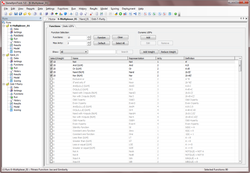
experiment with different combinations of functions. The Function
Selection Tools of GeneXproTools help you with experimenting with
different function sets very quickly either through the
Random
button in the Functions Panel or by selecting certain sub-sets of
functions.
Note that GeneXproTools automatically balances your function set
according to the number of input variables in your data,
therefore you just have to select the set of functions for your problem and
then choose their relative proportions by choosing their weights.
Built-in Logical Systems
GeneXproTools allows you to design logic circuits using a
total of 258 built-in
logical functions,
which are the logical functions at the disposal of
the
learning algorithms and also part of the basic Boolean grammar of
all built-in
programming languages or grammars (Ada, C, C++, C#, Excel VBA, Fortran, Java, Javascript, Matlab,
Octave, Pascal, Perl, PHP, Python, Visual Basic, VB.Net,
Verilog, and VHDL). But it also allows you to redesign immediately
the generated circuits using six different kinds of
logical systems
(All Gates, Not-And-Or Only, Nand Only, Nor Only, Mux System,
and Reed-Muller System). This means that for all these systems a corresponding
built-in grammar exists in all the programming languages supported by GeneXproTools.
These grammars can be used to automatically generate Not-And-Or Only, Nand Only,
Nor Only, Mux Only, and Not-And-Xor circuits.
User Defined Functions
Despite the great diversity of GeneXproTools
built-in
logical functions, some users
sometimes want to model with different ones.
GeneXproTools gives the user the possibility
of creating custom functions (called
Dynamic UDFs and represented as DDFs
in the generated code) in order to design circuits with them.
Note however that the use of custom functions is
computationally demanding, slowing considerably the evolutionary process and therefore should be used with moderation.
By selecting the Functions Tab in the Functions Panel, you have full access to
all the available functions, including all the
functions you've designed and all the
built-in
logical functions. It's also in the Functions Panel
that you add
your custom functions (Dynamic UDFs or DDFs) to your
modeling toolbox.
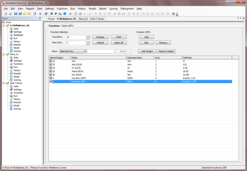
To add a custom function to your function set, just check the checkbox on the Select/Weight column and
select the appropriate weight for the function (the weight determines the probability of each function being drawn
during mutation and other random events in the creation/modification of
logic circuits).
By default, the weight of each newly added function is 1, but you can increase the probability of a function being included in your
logic circuits by increasing its weight in the Select/Weight column. GeneXproTools automatically balances your
function set with the number of input variables in your data,
therefore you just have to select the set of logical functions for your problem and then choose their relative
proportions by choosing their weights.
To create a new custom function, just click the Add button on the Dynamic UDFs frame and the
DDF Editor appears. You can also edit old functions
through the Edit button or remove them
altogether from your modeling toolbox by clicking
the Remove button.
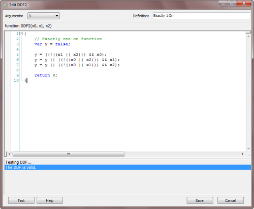
By choosing the number of arguments (minimum is 1 and maximum is 4) in the
Arguments combobox, the function header appears
in the code window. Then you just have to write the body of the function in the code editor. The code must be in JavaScript and can be
conveniently tested for compiling errors by clicking the Test button.
In the Definition box, you can write a brief description of the function for your future reference. The text you write
there will appear in the Definition column in the Functions Panel.
Dynamic UDFs are extremely powerful and interesting tools as they are treated exactly
like the built-in functions of GeneXproTools and therefore can be used to model
all kinds of relationships not only between the original variables but also between
derived features created on the fly by the learning algorithm. For instance, you can
design a DDF so that it will model four expressions
XOR-ed together, that is,
DDF = (expression 1) XOR (expression 2) XOR (expression 3)
XOR (expression 4), where the value of each
expression will depend on the context of the DDF in
the program.
 |
Creating Derived
Inputs/Variables |
Sometimes it is fundamental to use complex building blocks to
build even more complex ones, and
GeneXproTools allows you to design your own basic building
blocks (called Static UDFs or just UDFs in GeneXproTools).
These building blocks might represent any kind of
logical expression (not just functions of 1-4 arguments
like the DDFs described in the
previous section) and are
therefore ideal to design complex logic circuits composed of several simpler
components.
Derived variables or new inputs can be easily created in GeneXproTools
from the original inputs.
They are created in the Functions Panel, in the Static UDFs Tab.
The code for the UDFs must be in JavaScript and is written in the
Edit UDF window
(in the Functions Panel, select the Static UDFs Tab and then click
the Add button in the Static UDFs toolbox).
Historically, derived variables were called
UDFs or User Defined Functions
and in GeneXproTools they are represented as UDF0, UDF1, UDF2, and so on. Note however that
UDFs are in fact new inputs derived from the original
inputs in the training and test datasets.
Like DDFs, they are implemented in JavaScript using the JavaScript editor of GeneXproTools.
These user defined inputs are then used by the learning algorithm exactly as
the original inputs, that is, they are incorporated into the evolving
circuits
adaptively, with the most important being chosen and selected according to
how much they contribute to the performance of each
logic circuit.
 |
Exploring the Learning Algorithms |
GeneXproTools uses two different learning algorithms for
Logic Synthesis. The first – the basic gene expression algorithm
or simply
Gene Expression Programming (GEP) –
does not support the direct manipulation of random numerical constants (0's and 1's in this case),
whereas the second – GEP with Random Numerical Constants or
GEP-RNC
for short – has a facility for handling them
directly. These two algorithms search the solution landscape
differently and therefore you might wish to try them both on
your problems.
Taking into consideration not only the slightly higher complexity of the
GEP-RNC algorithm but also the fact that both these algorithms produce
equally elegant circuits, GEP is the default learning algorithm in GeneXproTools
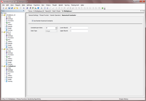
for Logic Synthesis problems. However, you can activate the GEP-RNC
algorithm in the Settings Panel -> Numerical Constants by
checking the Use Random Numerical Constants checkbox. In the
Numerical Constants Tab you can also adjust the range of the
constants (either 0 or 1 or both) and
the number of constants per gene.
The GEP-RNC algorithm is slightly more complex than
the basic gene expression algorithm as it uses an additional gene domain (Dc) for encoding the random
numerical constants. Consequently, this algorithm
includes an additional set of genetic operators (RNC
Mutation, Constant Insertion, Dc Mutation, Dc Inversion, Dc IS
Transposition, and Dc Permutation) especially developed for handling random
numerical constants (if you are not familiar with these operators,
please use the default Optimal Evolution Strategy by
selecting Optimal Evolution in the Strategy combobox
as it works very well in all cases; or you can learn more about the
genetic operators in
the
Legacy Knowledge Base).
 |
Monitoring the Modeling Process |
While your circuits evolve, you can evaluate and
visualize the actual design process through the real-time
monitoring of different
model fitting charts and statistics in the Run Panel, such as
different Binomial Fitting Charts, the
Classification Scatter Plot, the
Classification Tapestry, the
Confusion Matrix,
the Classification Accuracy and the Fitness.
The evolutionary process can be stopped whenever you are satisfied with the results by
clicking the
Stop button or you can use one of the
stop conditions of
GeneXproTools for stopping the design process exactly when you see fit.
When the evolutionary process stops, you can use the best-of-run
circuit either for analysis or
for deployment. And if you are still not happy with the results, you can
continue to fine-tune your logic circuit by
clicking any of the optimization buttons
GeneXproTools provides: Continue, Simplify
or Complexify. Particularly useful in Logic
Synthesis is the simplification functionality which
allows you to find more compact solutions to your logic circuits.
 |
Simplifying Logic Circuits |
The whole business of logic circuit design revolves around finding the
most parsimonious circuits and GeneXproTools deals with this task excellently.
No matter what form your circuits are in (sum-of-products,
product-of-sums, NAND-only, NOR-only, AND-XOR-NOT-only, MUX-only,
and so on), you can feed them to GeneXproTools and let it have a go
at simplifying them. The results of the simplification process can be conveniently
observed in the Run Panel where both the size and number of literals
are plotted during simplification.
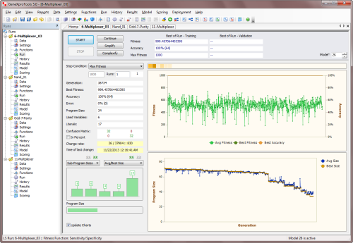
GeneXproTools allows you to simplify an existing
logic circuit (either
created with GeneXproTools or with another modeling
technology) either by clicking the
Simplify button in the Run
Panel or by turning on the Parsimony
Pressure in the Fitness Function
Tab and then clicking Continue or
Simplify in the
Run Panel. GeneXproTools allows you
to adjust the parsimony pressure you
exert on the size of the evolving
circuits, but bigger circuits can always
appear during evolution if the gain in fitness trumps
the smaller size.
But if your logic circuit is already a perfect
solution, its fitness can only improve by becoming
more and more compact.
For logic circuits created outside GeneXproTools or for GeneXproTools
circuits modified by the user in the Change Seed Window, the starting
logic circuit is fed to
the learning algorithm through the Change Seed Window where both the fitness and structural soundness
of the circuit are tested.
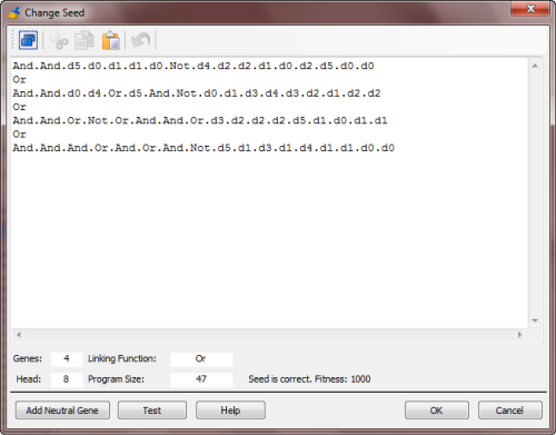
Then, in the Run Panel, by clicking the
Simplify button, an evolutionary process starts in which all the subsequent
circuits will be descendants of the
circuit you want to simplify. Keep in mind, however, that the
simplification algorithms GeneXproTools
uses are evolutionary
in nature and logic circuits continue
to be selected primarily by fitness.
This means that their
complexity might even increase temporarily if the gain in fitness outweighs
the loss in simplicity. But if your logic circuit is
already a perfect solution, its fitness can only
improve by becoming more and more compact.
For logic circuits created in the
GeneXproTools environment, you just have to
select the circuit you want to simplify (either the
best-of-run or an intermediate solution) and then
click Simplify in the Run Panel and let the algorithm create
better descendants not only in terms of fitness but also in terms of
size.
 |
Model Evaluation & Testing |
While your logic circuits are being created by the learning algorithm, you can evaluate and
visualize the actual design process through the real-time
monitoring of different charts and statistics
in the Run Panel such as the Classification Scatter Plot,
the Classification Tapestry
and the
Confusion Matrix.
Comparing Actual & Predicted Values
In the Results Panel you can further evaluate your
logic circuits for both the training and validation
datasets, using different model fitting charts
and additional
measures of fit, such as the
sensitivity,
specificity, recall, precision and Matthews
correlation coefficient.
Additionally,
GeneXproTools offers two different ways of analyzing and comparing the output of your
logic circuits with the actual or target values both for the training and
validation/test datasets.
In the first, the Target or actual values are listed in a
Table side by side with the predicted values or
Model output.
In the second, the target and predicted values are
plotted using different Model Fitting Charts for easy visualization,
including the Classification Tapestry, the
Classification Scatter Plot and different Binomial
Fitting Charts.
Evaluating Performance
GeneXproTools allows a quick and easy assessment of a wide
range of statistics for measuring the goodness of fit.
Most of these
measures of fit are immediately computed and shown
in the Statistics
Report every time you
go to the
Results Panel
(namely, the
classification error,
classification accuracy,
confusion matrix,
sensitivity,
specificity,
positive predictive value,
negative predictive value,
recall,
precision,
F1 measure,
Jaccard
similarity,
Matthews correlation coefficient,
Pearson correlation
coefficient,
R-square and the
root mean squared error).
These and other measures of fit (namely,
mean squared error, mean absolute error,
relative squared error,
root relative squared error,
relative absolute error)
are also shown in the Report Panel for the
active model, but you must
evaluate them first in the Results Panel.
 |
Modeling from Seed Circuits |
The whole business of logic circuit design revolves around finding
minimal logic circuits and GeneXproTools deals with this task excellently.
No matter what form your circuits are in (sum-of-products,
product-of-sums, NAND-only, NOR-only, AND-XOR-NOT-only, MUX-only,
and so on), you can feed them to GeneXproTools and let it have a go
at minimizing them. The results of the minimization process can be conveniently
observed in the Run Panel where both the size and number of literals
are plotted during minimization.

GeneXproTools allows the use of an existing logic
circuit (either generated by
GeneXproTools or by another modeling
tool) as the starting point of an evolutionary process
in order to create
better circuits.
For logic circuits created outside GeneXproTools or for GeneXproTools
circuits modified by the user in the
Change Seed Window, the starting circuit or
seed is fed to the algorithm through the
Change Seed Window where both the fitness and structural soundness of the
logic circuit are tested.
The Change Seed Window accepts
Karva Code only, so you must translate your
logic circuit into Karva notation
first in order to explore it in GeneXproTools.

Then, in the Run Panel,
by clicking any of the optimization buttons GeneXproTools provides (Continue,
Simplify and Complexify),
an evolutionary process starts in which all the subsequent
circuits will be descendants of the seed circuit you introduced.
Note, however, that if your starting logic circuit has a very small fitness, you risk losing it early in the run
as better logic circuits could be randomly created by GeneXproTools, leaving your seed behind.
For logic circuits created in the
GeneXproTools environment, the seed
(the active model) is fed
automatically to the algorithm every
time you click Continue, Simplify
or Complexify in the Run
Panel.
 |
Adding a Neutral Gene |
The addition of a neutral gene to a logic
circuit
(in logic terms, it’s like OR-ing an expression with zero or
AND-ing with one) might seem at first sight the wrong thing to do
as we are usually interested in creating minimal
logic circuits. But one
should look at this as modeling in progress as this allows us to tackle a complex problem incrementally.
Indeed, being able to introduce extra terms into your
evolving circuits is a powerful modeling tool and
GeneXproTools allows you to do that by selecting
Add Neutral
Gene in the Model menu or through the
Change Seed Window.
For instance, by choosing OR as linking function,
you could use a different gene for each minterm of
your circuit, and then try and evolve a more
parsimonious solution from there.
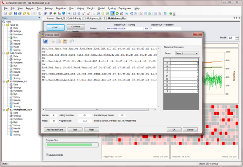
When you
click the Add Neutral Gene button in the
Change Seed window, you will see a neutral gene being added to your
logic circuit
(in the example above, the last gene was
OR-ed with itself). By doing this, you are giving the
learning algorithm more room to play and, hopefully, a
better circuit will evolve.
Neutral genes can also be introduced automatically
as part of a modeling strategy when you turn on the Complexity Increase
Engine of GeneXproTools, which is the topic of the next section.
 |
Complexity Increase Engine |
GeneXproTools also allows you to introduce neutral genes automatically
during a run by activating the
Complexity Increase
Engine in the Settings Panel -> General Settings Tab.
Whenever you are using the Complexity Increase Engine of GeneXproTools, you must fill the
Generations Without Change box to set the period of time you think acceptable for evolution to occur without improvement in best fitness, after which
a mass extinction and a neutral gene (an extra
neutral term) is automatically added to your
logic circuits; the Number of Tries corresponds to the
number of consecutive evolutionary epochs (defined by the parameter
Generations Without Change) you will allow before a neutral gene is
introduced in all evolving circuits; in the
Max Complexity box you write the maximum number of terms (genes) you’ll allow in your
logic circuits and no other terms will be introduced
beyond this threshold during the run.
The Complexity Increase Engine of GeneXproTools
is a very powerful modeling tool as
it helps the learning process
through the gradual increase of more
building blocks. However, when you are
done with the design don't forget to
simplify the final circuit to get
rid of the redundant elements that
might have accumulated during
evolution.
 |
Generating the Model Code |
In the Model Panel you can see
and analyze the code of your logic circuits not only in the programming language of
your choice but also as a diagram representation or expression tree.
GeneXproTools includes 18 built-in programming
languages or grammars for Logic
Synthesis.
These grammars allow you to generate code automatically in
some of the most popular programming
languages around, namely Ada, C, C++, C#, Excel VBA, Fortran, Java, JavaScript, Matlab,
Octave, Pascal, Perl, PHP, Python, Visual Basic, VB.Net, Verilog, and VHDL.
But more importantly, GeneXproTools also allows you
to add your own programming languages through
user-defined grammars, which can be easily
created using one of the built-in grammars as
template.
Visualizing Logic Circuits as Expression Trees
GeneXproTools includes a parse tree generator that automatically converts
the native
Karva code of your logic circuits into diagram representations or
expression trees, allowing a
quicker and more complete
understanding of their Boolean structure. By placing the cursor over each node of the expression tree,
you have access to the label of each input and its index,
the value of each constant and the definition of each function.
Generating Code Automatically Using GeneXproTools Built-in Grammars
GeneXproTools supports a total of 18
built-in programming languages so that the
logic circuits evolved by
GeneXproTools in its native
Karva code
can be automatically translated into some of the
most commonly used programming languages
(Ada, C, C++, C#, Excel VBA, Fortran, Java, JavaScript, Matlab,
Octave, Pascal, Perl, PHP, Python, Visual Basic, VB.Net, Verilog, and VHDL). Furthermore, for all languages, the generated
code can be automatically transcribed to six different logical
systems (All Gates, Not-And-Or Only, Nand Only, Nor Only, Mux System, Reed-Muller System)
using six different Boolean grammars. This code can then be used in other applications
to deploy the logic circuit.
Generating Code Automatically Using User Defined Grammars
GeneXproTools allows the design of
User Defined Grammars so that the logic
circuits evolved by
GeneXproTools in its native
Karva code
can be automatically translated into the programming
language that you need. Indeed, if you need to
generate model code in a programming language other
than the 18 built-in
programming languages of
GeneXproTools available for Logic Synthesis (Ada, C, C++, C#, Excel VBA, Fortran, Java, JavaScript, Matlab,
Octave, Pascal, Perl, PHP, Python, Visual Basic, VB.Net, Verilog, and VHDL), you can easily create your own grammars to generate code
automatically in as many languages as you need.
As an illustration, the All Gates VHDL grammar of GeneXproTools is shown
here.
Other grammars may be easily created using this or other GeneXproTools
built-in grammars as reference.
See Also:
Related Tutorials:
Related Videos:
Last modified: November 24, 2013
Cite this as:
Ferreira, C. "Logic Synthesis." From GeneXproTools
Documentation – A Gepsoft Web Resource.
http://www.gepsoft.com/GeneXproTools/LogicSynthesis.htm
|

